
Service Insertion and Service Chaining Defined

Service insertion refers to the adding of networking services, such as firewalls or load balancers, into the forwarding path of traffic. Service chaining builds on service insertion, allow the linkage of multiple services in a prescribed manner, such as proceeding through a firewall then an IPS, and finally malware protection before forwarding to the end user.
Within the datacenter, Layer-2 (L2) and Layer-3 (L3) approaches have been used to varying degrees for service insertion. SD-WANs bring SDN principles of service insertion to the wide area network.
Layer-2 Service Insertion
With flat networks, services can be inserted by bridging together two VLANs, such as with VLAN chaining. When users are in VLAN 1, for example, they can readily access the servers in VLAN 1. If we’d like to insert a local firewall for a group of stations, for example, we can group those stations into a separate VLAN. The traffic from VLAN 2 will be intercepted by the switch and sent to the service being inserted, in this case a firewall, for forwarding onto VLAN2.
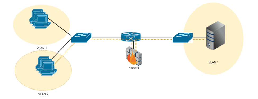
There are several problems with such an approach. Forwarding traffic based on VLAN tags means that it becomes very difficult to insert the service for some users and not others in that VLAN. It’s impossible to apply the service based on individual applications. Finally, spanning tree loops and other network issues can disrupt the network.
Layer-3 Service Insertion
With L3 service insertion, network services in the datacenter are inserted at the router. Instead of chaining VLANs, service insertion is done with subnets and virtual route forwarding (VRF). Users in Subnet #1 send traffic to their router that does an L3 lookup and forwards packets to the servers in Subnet #2. To direct some users to a firewall service, for example, a route policy on the router would forward traffic to Subnet #3. The firewall would apply the necessary policies and route the traffic (assuming it’s permitted) back to the router on subnet #4 for delivery onto the server in subnet #2.
Such an approach is common in many datacenters. Virtual route forwarding (VRF) is typically enabled with a VRF for one side of the router (Subnet .#1 in this case) and a VRF on the other side of the router (VRF #2).
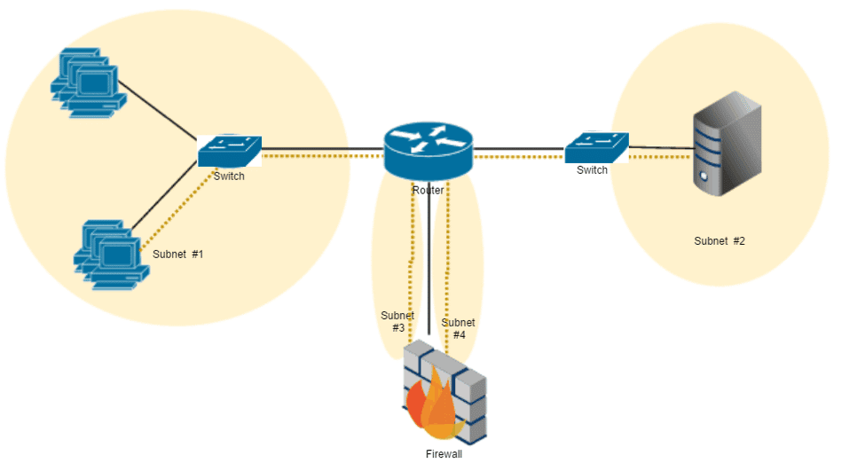
L3 service insertion address the challenges of L2, but poses it’s own challenges. All traffic must pass through the firewall, creating scaling issues. The architecture becomes more complicated as well when the service being inserted is not physically near the forwarding path.
SD-WAN Service Insertion
With SD-WAN service insertion, the resource is located in another location on the SD-WAN overlay. Implementations will vary but in general the availability of a resource is advertised to the nodes on the SD-WAN. Policies are created identifying the traffic to be forwarded to the resource and pushed out to the SD-WAN nodes. As traffic enters the SD-WAN, the nodes identify the traffic, looks up the forwarding policy, and directs the data to the tunnel associated with the proscribed resource. The SD-WAN node on the receiving end sends the traffic to the defined resource(s) before forwarding onto the destination. Traffic inspection and security enforcement is applied by the shared resources, in this case an IPS, and the traffic is forwarded onto the Internet.
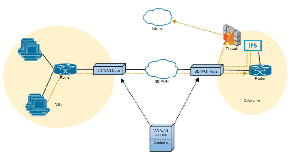
SD-WAN service insertion allows for the sharing of resources, which might otherwise not be available to some offices. However, bringing the traffic to the resource may be infeasible in some WAN architectures due to the distances and resulting latency between the locations.
Related Articles
What Consistent Leadership Across SSE, SD-WAN, and SASE Signals

Gradual by Design: What the Cloudflare Outage Reveals About Robust SASE Architecture and Operations

Resilient by Design: Cato’s Visibility and Backbone Performance Through the AWS Outage